Analyzing reflash routines Part 3 (Jaguar AJ27 specific)
In the last post we analyzed the behavior of the TPU bootcode for both processors, and the procedure to ‘unlock’ CPU1 phase 2 canbus commands, using a security procedure. Once the phase2 commands are unlocked, CPU1 executes a loop to listen for these commands. Note that as mentioned in the last post, if no command is received within 10 ms of the successful unlock process, the commands will be locked out again. A summary of the basic commands available is in the table below.
| basic command | byte 2 options | comments |
|---|---|---|
| 0x31 | 0xa0, 0xa2, 0xa5 | upload request commands |
| 0x32 | 0xa2, 0xa5 | upload validation commands |
| 0x34 | 0x80 | set upload address target location |
| 0x36 | - | upload data bytes |
| 0x37 | 80 | finalize upload |
| 0x3f | - | ping |
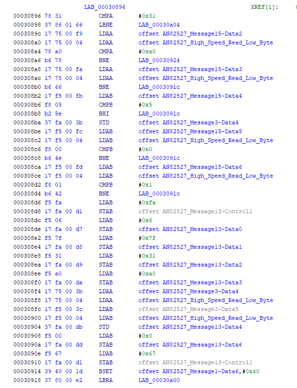
1) Command 31 is implemented starting at address 308fc
- 31 a0 pp qq rr ss - the subsequent 4 bytes of the message are examined. Byte 3 (pp) must be 0, byte 4 (qq) must be <= 5, byte 5 (rr) must be 0, byte 6 (ss) must be 1. So the command format is 06 31 a0 00 pp 00 01, where pp is a value between 0 and 5. The value pp is stored in message3-data5. Assuming the checks pass, a response 06 7f 31 a0 pp 00 is sent, and bit6 of message1-data6 is set
-
31 a0 summary - initializes a data upload to CPU1 RAM, and indicates the number of 1k blocks to be uploaded. In all cases, the full instruction used is 31 a0 00 05 00 01
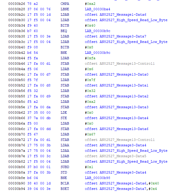
- 31 a2 - validates whether bit6 of message1-data6 is set (by message 31 a0 above)
-
summary - checks if the 1k uploads are progressing with no errors, and if confirmed, generates the response 06 7f 31 a2 00 00 00
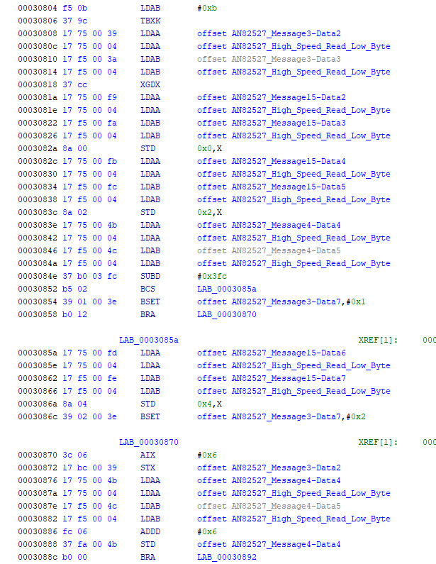
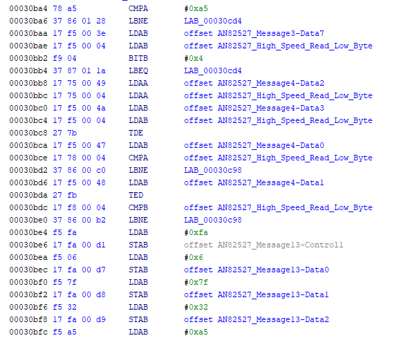
- 31 a5 pp qq - checks if all 1k blocks have been uploaded (bit 2 of message3-data7, as set by 31 a2). If so, then expected checksum (pp qq) is stored in message4-data0/1. Also, a 16 bit checksum is computed over addresses b0000-b13ff, and stored in message4-data2/3. Response is 06 7f 31 a5 pp qq 00. The checksum computation is shown below
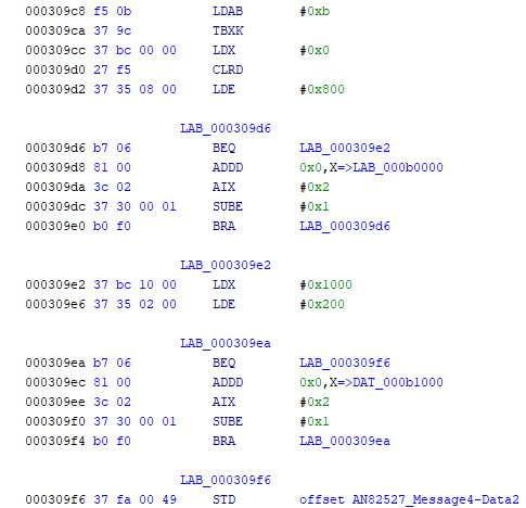
- 31 a5 summary - receives and stores expected checksum, and computes actual checksum of the 5k of data uploaded to CPU1 RAM
2) Command 34
- 34 80 pp qq rr ss tt - Check if bit6 message1-data6 is set - this is set by 31 a0 above. Checks that pp qq = 0x0400. Checks that rr = 0x0b and tt = 0. Checks that ss = 0x00, 04, 08, 0c or 10. If checks pass, store ss tt in message3-data2/3, and send response 06 7f 34 80 pp qq 00. Also clear bit0 and set bit3 of message3-data7. Bit0 enables message 36 when clear, and bit3 is subsequently cleared by message 37, which is required for message 32 a2 to execute.
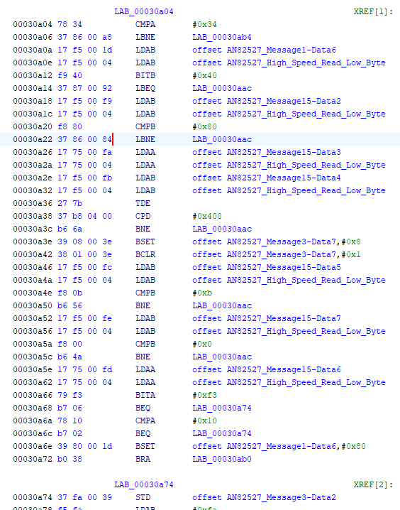
- 34 80 pp qq rr ss tt summary - set the target address for pp qq bytes of data upload to CPU1 RAM - pp qq must equal 0x0400 which is 1k bytes. Target address for the upload is rr ss tt, with valid addresses limited to 0x0b0000, b0400, b0800, b0c00, b1000
3) Command 36
- 36 pp qq rr ss tt uu - Check if bit6 message1-data6 is set - this is set by 31 a0 above. Check if bit0 message3-data7 is clear (cleared by message 34, set in this routine when 171 consecutive 0x36 messages have been uploaded, i.e. 1k bytes of data). The 6 bytes (pp - uu) are stored starting at the CPU1 RAM address pointed to by (0xb0000 + message3-data2/3), which is the address setup using message 34. On each subsequent message 36, the target address (as stored in message4-data4/5) is incremented by 6, since 6 bytes are received in each message. On receipt of the 171st message 36 (message4-data4/5 >= 0x3fc), only the first 4 bytes (pp -ss) are stored, and bit0 of message3-data7 is set, to indicate completion of the 1k bytes upload (1024 = 170*6 + 4). No response is generated to receipt of a message 36.
- Note that after receipt of each of the first 170 transmissions of message 36, bit1 of message3-data7 is set. This causes the watchdog timer to be loaded with a value of 850 us rather than 10ms, and then bit1 is cleared. This means that each message 36 must be received within 850 us of the previous message, otherwise the whole procedure will be voided. The watchdog timer will be restored to the usual 10 ms value once the last (171st) message 36 is received.
- 36 pp qq rr ss tt uu summary - used to upload 1024 bytes to CPU1 RAM, 6 bytes (pp - uu) at a time, using 171 consecutive transmissions of message 36
4) Command 37
- 37 80 - Check if bit6 message1-data6 is set - this is set by 31 a0 above. Check if bit3 message3-data7 is set - this is set by 34 80 above. Send response 06 7f 37 80 00 00 00, and clear bit3 of message3-data7, which will allow message 32 a2 to execute.
- summary - clears the target address provided by message 34, and enables validation that a 1k block has been uploaded using message 32 a2
5) Command 32
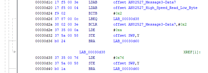
- 32 a2 - Check if bit6 message1-data6 is set - this is set by 31 a0 above. Check if bit3 message3-data7 is clear - this is cleared by message 37 80 above. Send response 06 7f 32 a2 00 00 00. Decrement message3-data4/5, which was initialized (to 5) by message 31 a0 above - this is a counter that counts down the number of 1k blocks that have been uploaded. If the counter is decremented to 0 (i.e. all 5 blocks uploaded) then set bit2 of message3-data7, which will allow message 31 a5 and 32 a5 to execute.
- 32 a5 - Check if bit2 message3-data7 is set - this is set by 32 a2 above. Using results of message 31 a5 above, compare expected checksum stored in message4-data0/1 with computed checksum stored in message4-data2/3.
-
If they are equal (checksum passed), send response 06 7f 32 a5 00 00 00. Reconfigure RSPI and jump to address b0000, i.e. start executing the uploaded program
-
If they are not equal (checksum failed), send response 06 7f 32 a5 00 5b 63. Clear bit2 of message3-data7, which disables checksum upload/computation and validation.
-
32 a5 summary - validate checksum of 5k of code uploaded to CPU1 RAM, starting at b0000, and if checksum is valid, execute the uploaded code
To wrap things up for this post, in order to upload the “MainBoot” program into CPU1 RAM, the procedure is as follows, noting that timeouts must be respected.
- prepare to upload five 1k code blocks using message 31 a0
- for (pp = 0x00, 04, 08, 0c, 10)
- send target address 0x0bpp00 using message 34 80
- for n = 0 to 170, upload 1k bytes of data using message 36, 6 bytes at a time
- send upload finished using message 31 a2
- send reset target address using message 37 80
- send block upload complete, using message 32 a2
- compute uploaded code checksum, and send expected checksum, using message 31 a5
- validate checksum and execute uploaded code from address 0x0b0000 in CPU1 RAM, using message 32 a5
Once the “MainBoot” is executing in CPU1 RAM, it provides the capabilities to upload and execute the “SubBoot” to CPU2, leveraging the TPU bootcode that is still executing in CPU2. The MainBoot and SubBoot programs, once both uploaded, provide the capabilities to read, erase, and reflash the EEPROM contents for CPU1 and CPU2. These items will be investigated in the next post.