Analyzing reflash routines Part 2 (Jaguar AJ27 specific)
In the last post we established that CPUs boot into the TPU EEPROM area on reset, and then continue to execute if the flash communications port and flash programming voltage are activated.
The code for CPU2 is fairly simple. After basic initializations, there is an execution loop which proceeds through the following steps:
1) Check serial port for a new incoming byte from CPU1. If new data available, load it into register B, and load X with value 0x0b8008
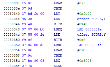
2) If incoming byte has value in range 0-5, send back a byte to CPU1 over serial, as below. Also, for incoming values 1-5, write 0 to address 0x0b1000
| incoming byte | response byte read from address | comment |
|---|---|---|
| 0 | 0xb8008 | eeprom signature byte 0 |
| 1 | 0xb8009 | eeprom signature byte 1 |
| 2 | 0xb800a | eeprom signature byte 2 |
| 3 | 0xb800b | eeprom signature byte 3 |
| 4 | 0xb800c | eeprom signature byte 4 |
| 5 | 0xbfffe | eeprom erase count |
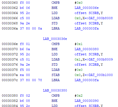
3) If incoming byte has value of 6 or 0x0c then write 1 to address 0x0b1000
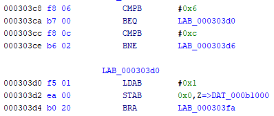
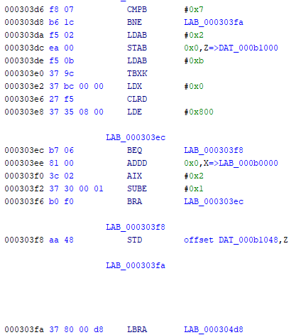
4) If incoming byte has value of 7 then
- write 2 to address 0x0b1000
- compute 16 bit checksum over addresses 0x0b0000 - 0x0b0fff
- store checksum at address 0x0b1048
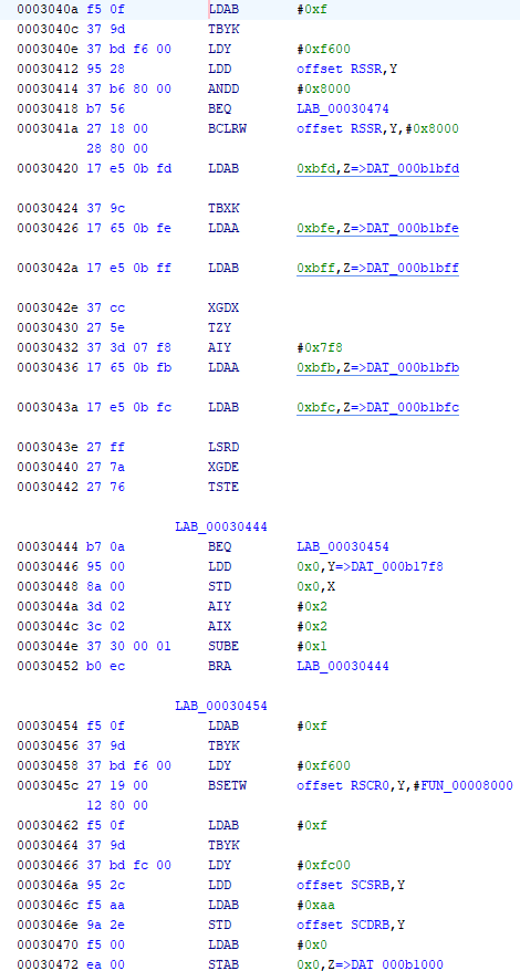
5) Check value stored at address 0x0b1000 (which will be 0, 1, or 2 based on actions from serial port receive byte as above)
6) If value is 0 then do nothing
7) If value is 1, then:
- check if the 1007 byte RSPI data transfer from CPU1 is complete (CPU1 data addresses 0xb13f0-0xb17f7 are copied to CPU2 data addresses 0xb17f8-0xb1bff)
- If so, create a 24 bit “base address” from bytes b1bfd/e/f
- and create a “byte counter” from address b1bfb/c
- Then copy a block of bytes, starting at address 0x0b17f8 (start of transferred block) and length equal to “byte counter”, to address starting at “base address”
- send byte 0xaa to CPU1 over serial port B
- write 0 to address 0x0b1000
- In summary this allows a block of up to 1k bytes to be transferred from CPU1 to CPU2, and then loaded into a target (RAM) address in CPU2
8) If value is 2, then:
- check if the 1007 byte RSPI data transfer from CPU1 is complete (CPU1 data addresses 0xb13f0-0xb17f7 are copied to CPU2 data addresses 0xb17f8-0xb1bff)
- compare checksum word computed and stored at address 0x0b1048 (from 4. above) with value received from CPU1 at address 0x0b1bfb
- if they are equal, then send byte 0x50 to CPU1 over serial port B (checksum passed)
- if they are not equal, then send byte 0xfa to CPU1 over serial port B (checksum failed)
- write 0 to address 0x0b1000

9) Maintain watchdog signal to prevent processor reset
In summary, the TPU code in CPU2 allows
- eeprom signature and erase count to be sent to CPU1
- 4k data block to be transferred from CPU1 to CPU2, with checksum validation
- multiple data blocks up to 1k size received from CPU1 and loaded into arbitrary address
- checksum computed over address range 0x0b0000 - 0x0b0fff (4k bytes) and compared with value sent from CPU1, with result sent back to CPU1
Next let’s look at the CPU1 TPU code. From the previous post, a summary level view of the main program loop was given as
- (one time) After a short timeout, send 0 over serial port B to CPU2
- Check if a byte is received from CPU2 over the serial port B
- Check if a message is received over canbus (from ID 0x20)
- Check if software watchdog timer has counted down to zero, and if so reset some flags, and restart timer
- Use real time counter to maintain power supply hardware watchdog signal
Also, as a reminder, the CPU1 code uses the canbus chip (AN82527) message ram for temporary storage of data. The AN82527 is mapped to base address 0x80000 in CPU1, and has an address space of 256 locations.
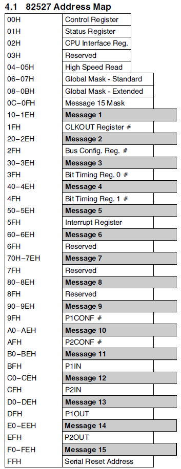
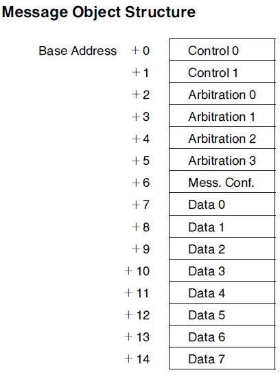
The 15 message objects each contain 16 bytes, and only message objects 13 and 15 are used for actual canbus communications by the TPU bootcode. So the other message objects are spare for other uses, and some of the message data bytes 0-7 within these message objects are as used for general storage by the TPU code.
1) For transfer of data from CPU2 to CPU1 (step 2 from CPU2 covered above), this is illustrated in the code snapshot below. Some bit flags stored in canbus RAM location message1-data6 ensure that the serial data exchange procedure is only executed once. The incoming byte over serial is stored in register E (at 3044a). The value of the byte stored in canbus RAM location message1-data1 counts how many bytes have been received. This value is tested, and used to store the 5 received bytes from CPU2 in canbus RAM locations message2-data0 to message2-data4 and the last in message1-data1.
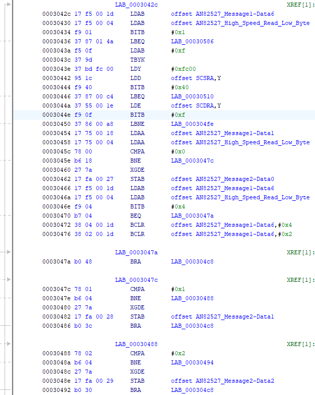
In order to progress the serial exchange through the 6 bytes of transfer, the value of message1-data1 counter is incremented on each iteration of the loop at 304e0, sent to CPU2 over serial B at 304f4, and checked at 304d6 so that the loop is stopped once its value reaches 5 (all 6 bytes retrieved from CPU2).
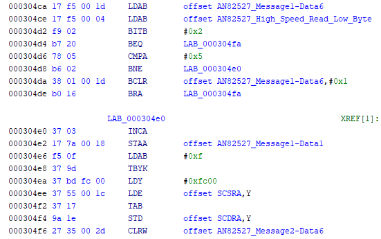
At completion, the data has been transferred and stored as in the table below
| message1-data1 | CPU2 memory byte | comment | CPU1 storage location |
|---|---|---|---|
| 0 | 0xb8008 | eeprom signature byte 0 | message2-data0 |
| 1 | 0xb8009 | eeprom signature byte 1 | message2-data1 |
| 2 | 0xb800a | eeprom signature byte 2 | message2-data2 |
| 3 | 0xb800b | eeprom signature byte 3 | message2-data3 |
| 4 | 0xb800c | eeprom signature byte 4 | message2-data4 |
| 5 | 0xbfffe | eeprom erase count | message1-data1 |
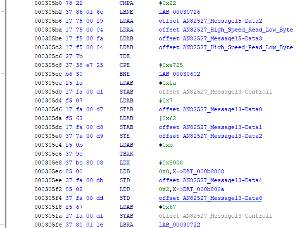
2) The loop to check canbus messages received from ID 0x020 (configured to message object 15) starts at 30586. There are two phases to this loop, depending on the value of flag in message1-data6 bit 3. The first phase only checks for three incoming messages, with byte1 values 0x22, 0x27, and 0x3f (noting that byte0 defines the length of the message). Checking for 0x22 messages starts at 305b0, and if byte1 is equal to 0x22 then the next two bytes are checked. The first value to be checked is 0xe725, and if this is a match, then a response message is created (using message object 13, with ID 0x030). The response sends back the first four bytes of CPU1 eeprom signature (at addresses 0x0b8008-b).
Additional message 0x22 variants are used to return other data, as below. CPU2 data is as transferred via the serial port in step 1 above.
| request message | response message | comment |
|---|---|---|
| 03 22 e7 25 | 07 62 e7 25 pp qq rr ss | pp-ss are CPU1 eeprom signature bytes 0-3, from addresses 0x0b8008-b |
| 03 22 e7 26 | 04 62 e7 26 pp | pp is CPU1 eeprom signature byte 4, from address 0x0b800c |
| 03 22 e7 27 | 07 62 e7 27 pp qq rr ss | pp-ss are CPU2 eeprom signature bytes 0-3, from addresses 0x0b8008-b |
| 03 22 e7 28 | 04 62 e7 28 pp | pp is CPU2 eeprom signature byte 4, from address 0x0b800c |
| 03 22 e7 29 | 04 62 e7 29 pp | pp is CPU1 eeprom erase count, from address 0x0bfffe |
| 03 22 e7 2a | 04 62 e7 2a pp | pp is CPU2 eeprom erase count, from address 0x0bfffe |
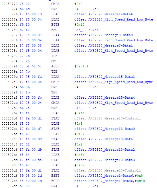
Checking for message 0x3f is at 307ec. This is basically a ‘ping’, and a simple response is sent
| request message | response message | comment |
|---|---|---|
| 01 3f | 02 7f 00 | simple ping response |
Message 27 is processed starting at 30726. It is a security procedure which unlocks the second phase of canbus messages. There are two steps to the security process. First, a request for a seed word is sent (using 02 27 01), and the reply contains the seed word. The seed word is a random value, generated using CPU1 real time counter). The requesting process and CPU1 then both compute a word result using the seed word and a security algorithm. The requesting process sends this result word ppqq (using 04 27 02 pp qq), and this is checked against the result that CPU1 computed independently. If they match, then phase 2 canbus commands are unlocked (controlled by the flag stored in message1-data6 bit 3). If the check fails, there is no response, and the seed value is cleared. The code for message 27 02 is at 30722. Additionally, a timer of about 10 ms is set when the seed code is generated, and the result word must be sent before this timer expires, otherwise the procedure fails and must be repeated. The unlock action for phase 2 commands will also expire in 10 ms if no new canbus messages are received within that interval.
A summary for message 27 is as follows
| request message | response message | comment |
|---|---|---|
| 02 27 01 | 04 67 01 pp qq | security process, request seed word ppqq |
| 04 27 02 rr ss | 03 67 02 34 | response only if rrss matches internal calculation |
The phase 2 commands will be analyzed in the next post.