OBD2 and UDS services over Canbus
A canbus message (ignoring for a moment multi-frame messages) can transmit/receive 8 data bytes. When requesting OBD2/UDS services over canbus
- the request is sent to the AJ27 ECU at canbus address 0x7e8
- the first data byte (data0) in the message specifies the number of following bytes (1-7)
- the second data byte (data1) specifies the OBD2 mode/UDS service requested (e.g. 0x22 for UDS service 22, extended PID request)
- any additional bytes (data2-7) are parameters of the message request
The AJ27 ECU will respond, if a response is necessary and enabled, by transmitting a message with canbus ID 0x7ec (i.e. 0x7e8 + 4, this is not typical standards behavior which would be to respond on 0x7e8+8 = 0x7f0). The format of the response message is:
- the first data byte (data0) in the message specifies the number of following bytes (1-7)
- the second data byte (data1) is the request byte + 0x40 ( e.g. 0x62 if service requested was 0x22), or 0x7f for an error/unknown response
- any additional bytes (data2-7) that are part of the message response
So to get into more details on OBD2/UDS services, we need to look at functions that are associated with receiving canbus messages with Canbus ID 0x7e8. From the previous post, this is AN82527 canbus controller message object 0x0c. If we use Ghidra to look at the mirror RAM block for data bytes received with object 0x0c, we see the following:
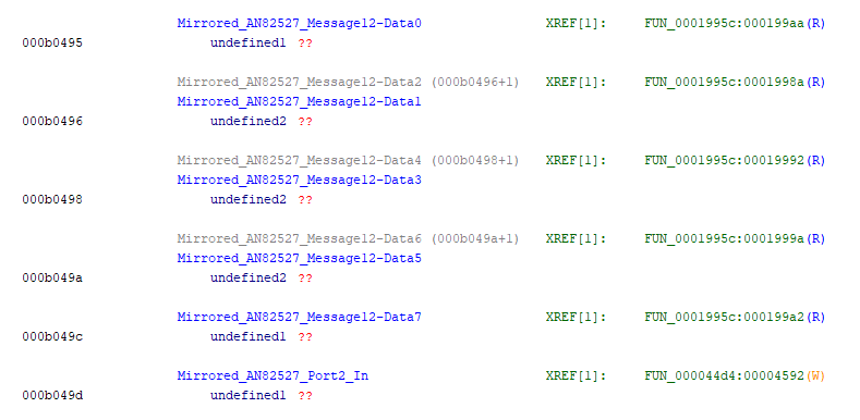
This indicates that the function we should be looking into is FUN 1995c. If we start to review this function, skipping some conditional branches etc. which can leave for another time, the main area of interest is as below:
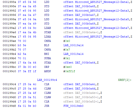
- starting at [1998a], store message bytes 1-7 in RAM block at 0xb0a45-b0a4b
- if data byte 0 (the length byte) is between 0-7 (which means it is not a multi-frame packet), then decrement its value by 1 and store in b0a44
- so b0a44 contains the number of message bytes, ignoring the initial length byte
- ignore for now - ORP, ANDP
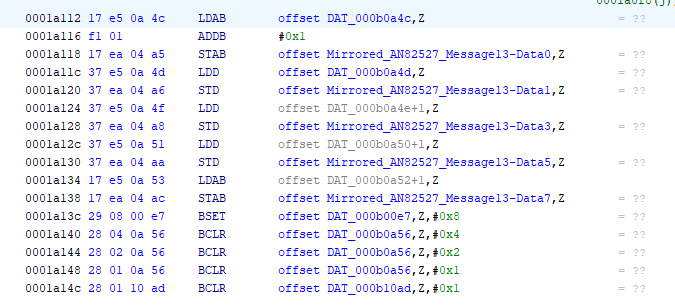
- clear RAM locations b0a4c-b0a53 (will be used to build the response message)
- JSR (Jump to Subroutine) 19eb0
Double clicking on FUN_00019eb0 to see the code there, at the start of the function we have:
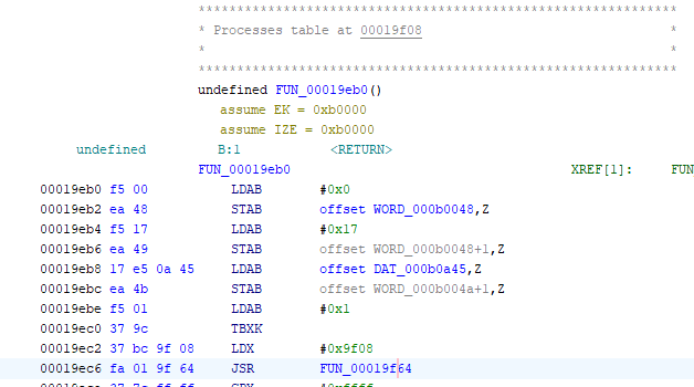
This is some setup code prior to calling FUN 19f64. (Note that RAM bytes at b0048-4d+ are typically used for local variables in this firmware)
- memory byte b0048 set to 0 (Starting index of table to search for match)
- b0049 set to 0x17 (ending index of table to search for match)
- b004b set to data byte1 of the message (value of target service to be matched)
- X set to 0x19f08 (base address of search table/jump table)
0x19f08 is the base address of a table of 0x17 locations. Each location contains a data structure of 3 elements as follows:
- Single byte - representing the OBD2/UDS service of this location
- Single byte - representing which CPU(s) implement this service
- Single word - representing an offset/jump address (from 0x10000) of the IC501 function, if supported, that implements this OBD2/UDS service
Function 19f64 will search the table (appears to be some variant of a binary/half interval search algorithm), attempting to match the target service value (in b004b) with the available services listed in the table. If a match is found then register B is set to element 2 byte, and register IX (lower 16 bits) is set to element 3 word. If there is no match, IX is set to 0xffff, and a response message is generated via FUN 1a152 which would contain the 0x7f error byte plus a read back of the original message.
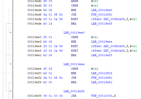
The byte value in element 2 is then masked off (to ensure it only represents values 0,1,2,3), and then the value tested.
- if 3, then call FUN 19ffc, then call FUN pointed to by element 3 (from the jump table) (use both IC501 and IC601 jump tables)
- if 1, then call FUN pointed to by element 3 (from the jump table) (use IC501 jump table0
- if 2, then call FUN 19ffc (use IC601 jump table)
- and if 0 (which would be an error), then continue as if no match was found
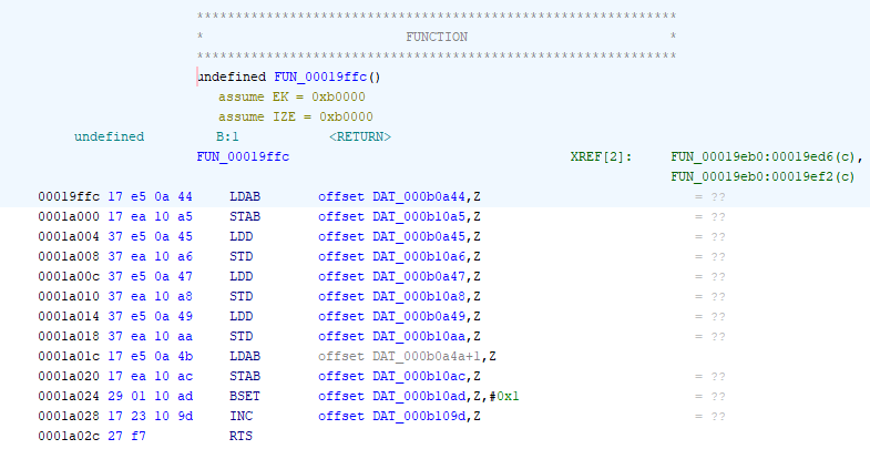
Function 19ffc uses the shared RAM block to forward the canbus message to IC601, using addresses b10a5-ac (and, though not shown here, IC501 can read the response message at b12b3-ba). If we skip over to the IC601/F27SD074.b68 file for a moment, we can discover that the equivalent jump table is at 0x120c4
Pulling all this together, across these two tables we have information that shows which canbus services are supported, and the identity of the functions on IC501 and IC601 which implement these services. This info is summarized in the table below. Note OBD2 mode 2 is missing, as it is only supported on serial, not on canbus.
| Service ID | FUN IC501 | FUN IC601 | |
|---|---|---|---|
| 1 | x | 1215e | Show real time data |
| 3 | x | 121c2 | Show Diagnostic trouble codes |
| 4 | x | 121f4 | Clear DTCs |
| 5 | x | 1222c | Test results for oxygen sensors (non CAN only) |
| 6 | x | 1229a | Test results for system monitoring (and oxygen sensors for CAN) |
| 7 | x | 122fc | Show pending DTCs |
| 8 | x | 12336 | Control operation of on-board system |
| 10 | 1a1ae | x | Diagnostic Session Control (controls which UDS services are available) |
| 12 | x | 123ce | ? TBD |
| 13 | x | 1249a | ? TBD |
| 14 | 1a1dc | 124cc | Clear diagnostic information (delete all stored DTC) |
| 20 | 1a296 | x | Stop diagnostic session control |
| 22 | 1a2c4 | 1261e | Read Data by Identifier (extended PIDs) |
| 23 | 1a4be | 127e8 | Read memory by address (restricted to ranges b0000 – b1bfc, b8000 – bfffc) |
| 27 | 1a520 | x | Security Access (enable use of security critical services via authentication) |
| 2f | 1a660 | 1283e | Input/Output control by identifier (per Service 22 IDs, many are locked by security services) |
| 31 | 1a8f2 | 12a5e | UDS - Routine Control? |
| 32 | 1a948 | 12aa0 | ? TBD |
| 33 | 1a9d6 | 12b50 | ? TBD |
| 35 | 1aa2a | x | Request upload (? output black box data ?) TBC |
| 37 | 1aa82 | x | UDS - Request transfer exit? TBC |
| 3f | 1aaa8 | x | ? TBD |
| b2 | 1aabc | x | ? TBD |
The initial objective from analyzing all this was to dig into service 22 extended PIDs, so the next step is to look into IC501 FUN 1a2c4
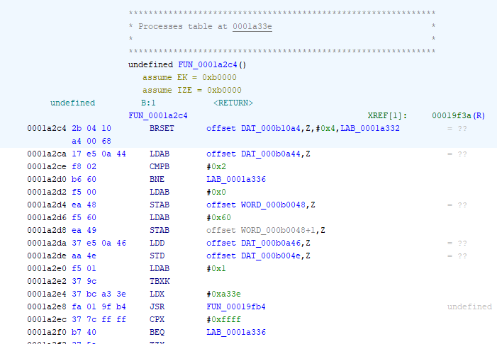
This is very similar to the jump table search for the target service. Again, there is some setup code prior to calling FUN 19fb4.
- memory byte b0048 set to 0 (Starting index of table to search for match)
- b0049 set to 0x60 (ending index of table to search for match)
- b004e (word) set to data byte2/3 of the service request message (value of target PID to be matched)
- X set to 0x1a33e (base address of search table/jump table)
Function 19fb4 is similar to the earlier search function 19f64, but searches using a 2 byte target value rather than one byte. If a match is found then IX (lower 16 bits) is set to an offset/jump address. If there is no match, IX is set to 0xffff, and a response message is generated via FUN 1a162 which would contain the 0x7f error byte plus a read back of the original message, as before.
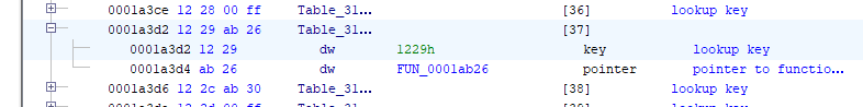
As an example of a lookup, let’s review extended PID 0x1229, Mass air flow meter voltage. The entry for this indicates it is supported by FUN 0x1ab26.
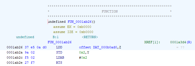
The code is fairly simple, loading the word value stored in 0xb0ad0, and storing it in memory at address Y+2. Y was setup in the calling function 1a2c4 which executes the service 22 jump table, to point to the response message that was being built, specifically to byte data3. So the value read from 0xb0ad0 is stored in the canbus response message. The response built then be (in hex): 04 62 22 aa bb, where aabb is the value read.
The response is transmitted via message 13 object, which is built by FUN 1a02e. This function is a bit more complex, because it has to also check if the response was sent back from IC601 rather than executed using IC501, and also deal with other issues like reading persistent data from eeprom storage.
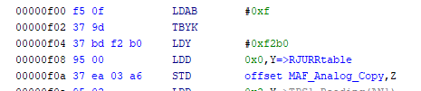
This analysis has revealed that MAF voltage reading is stored in the word at memory address 0xb0ad0. Normally, this would be the primary way to discover the identity of variable such as this. In our case, since we have a rough schematic of the ECU, we can cross check assumptions. The MAF output is connected to AN0/pin141 on IC501. The configuration of the Queued Analog to Digital Converter module for IC501 sets AN0 to channel 0.

Channel 0 is read and the 10 bit right justified value copied into address b03a6
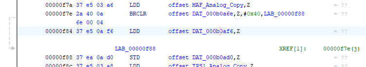
and then this value at b03a6 is read and stored in address b0ad0 (unless it is overridden by a value input via canbus service 2f, stored in b0af6). So the cross check is good, and MAF volts is indeed stored into address 0xb0ad0.
As a wrap up, the variable identities discovered using service 22 for this firmware load (F27SC074, F27SD074) are summarized in the table below.
| USD Service 0x22 parameter | Hex value | Bytes | IC501 FUN (F27SC074.b68) | IC601 FUN (F27SD074.b68) | IC501 Variable (F27SC074.b68) | IC601 Variable IC (F27SD074.b68) | |
|---|---|---|---|---|---|---|---|
| PIDS supported (1-0x20 – bit encoded) | 00 00 | 8 | 0 | 10DD0 | |||
| Monitor status since DTCs cleared. (Includes malfunction indicator lamp (MIL) status and number of DTCs.) | 00 01 | 1 | 10E3A | ||||
| Fuel system status | 00 03 | 2 | 3 | 1101A | b1082 | b12c2 | |
| Calculated load value | 00 04 | 1 | 4 | 11026 | Calculation – TBD | ||
| Engine coolant temperature | 00 05 | 1 | 5 | 1103A | 40 + (B1276 – 40)*5/8 (IC601 b1276 = IC501 b1036) | ||
| Short term fuel trim—Bank 1 | 00 06 | 1 | 6 | 11068 | b105e | b129e | |
| Long term fuel trim—Bank 1 | 00 07 | 1 | 7 | 11074 | b1072 | b12b2 | |
| Short term fuel trim—Bank 2 | 00 08 | 8 | 11080 | b1060 | b12a0 | ||
| Long term fuel trim—Bank 2 | 00 09 | 9 | 1108C | b1074 | b12b4 | ||
| Manifold absolute pressure sensor | 00 0B | 1 | B | 11098 | (b04fa – 0x2670) / 0xf5 | ||
| Engine RPM | 00 0C | C | 110C4 | b109e | b12de | ||
| Vehicle speed | 00 0D | D | 110D4 | b1050 | b1290 | ||
| Ignition timing advance (cylinder 1 bank 1) | 00 0E | 1 | E | 110E0 | b1052 | b1292 | |
| Intake air temperature | 00 0F | 1 | F | 110F0 | 40 + (B1277 – 40)*5/8 (IC601 b1277 = IC501 b1037) | ||
| Mass air flow | 00 10 | 2 | 10 | 1111E | (b128e * 0x9c40) / 0x10000 | ||
| Throttle position sensor | 00 11 | 1 | 11 | 11136 | (b1056 – 0x8000)*(0x100/0x28f6) (use either b1056 or alternate b1024) | ||
| Oxygen sensors present (in 2 banks) | 00 13 | 1 | 13 | 11156 | Constant 0x33 or 0x0 | ||
| Oxygen Sensor 2, A: Voltage, B Short Term Fuel Trim | 00 15 | 2 | 15 | 11168 | b12d4 based calculation, b12a6 | ||
| Oxygen Sensor 6, A: Voltage, B Short Term Fuel Trim | 00 19 | 19 | 11180 | b12d6 based calculation, b12a8 | |||
| OBD standards this vehicle conforms to | 00 1C | 1C | 11198 | constant, 0x2 or 0x3 or 0x6 | |||
| PIDs supported [21 - 40] | 00 20 | 4 | 20 | 111B2 | Constant 0x00001101 or 0x00000001 | ||
| O2 sensor equivalence ratio bank 1 upstream | 00 34 | 4 | 34 | 111D4 | b129e, b12f6 (IC501 b105e, b10b6) | ||
| O2 sensor equivalence ratio bank 2 upstream | 00 38 | 4 | 38 | 111EC | b12a0, b12f8 (IC501 b1060 , b10b8) | ||
| PIDs supported [41 - 60] | 00 40 | 40 | 11204 | Constant 0x0 | |||
| TBD | 02 00 | 200 | 12BA0 | TBD | |||
| Sensor power supply monitor | 12 04 | 2 | 1204 | 12C28 | b038a | ||
| Barometric pressure sensor | 12 06 | 2 | 1206 | 1AAEA | b0ae2 | ||
| Fuel tank pressure ñ vapor recovery system | 12 08 | 2 | 1208 | 1AAF4 | b103e | ||
| Speed ctrl set, Speed ctrl cancel | 12 0C | 120C | 12C34 | b0396, b0398 | |||
| ? Switched ignition volts/4 ? | 12 0D | 120D | 1AAFE | 12C48 | b0ad8 | b039a | |
| Throttle position sensor track 2 cpu 1 | 12 0E | 4 | 120E | 1AB08 | 12C54 | b0ad2 | b0380 |
| Pedal position sensor track 1 cpu 1 | 12 0F | 4 | 120F | 1AB12 | 12C60 | b0ad4 | b0384 |
| Evaporative purge valve | 12 11 | 1 | 1211 | 1AB1C | b106f | ||
| Pedal position sensor track 2 cpu 1 | 12 19 | 2 | 1219 | 12C6C | b0386 | ||
| Target throttle position | 12 1C | 2 | 121C | 12C78 | b1048 | ||
| Throttle position sensor track 2 | 12 1D | 2 | 121D | 12C84 | b0382 | ||
| EGR valve | 12 28 | 1 | 1228 | 12C90 | b0742 | ||
| Mass air flow meter | 12 29 | 2 | 1229 | 1AB26 | b0ad0 | ||
| Mass air flow sensor ground | 12 2C | 2 | 122C | 1AB30 | b0ae0 | ||
| Revs at IC601? | 12 2D | 122D | 12C9C | b0008 | |||
| Second fuel pump relay | 12 2E | 4 | 122E | 1AB3A | PortD bit 5 inverted, portMC bit 5 inverted, 0xff 0xff (fuel pump 2 relay, security acknowledge) | ||
| Camshaft signal monitor bank 1 cpu 1 and bank 2 cpu1, crank request, park/neutral position switch | 12 2F | 2 | 122F | 1AB68 | (Bit 6 park/neutral conf + bit 4 air assist close valve + bit 2 evap monitor + bit 0 ecm program flash comms control), (bit 7 CMPS 1 + bit 6 CMPS 2 + bit 2 engine crank monitor + bit 1 brake switch monitor + bit 0 ecm program flash comms control port) | ||
| Fast speed cooling fan, slow speed cooling fan, inertia switch, parketing brake switch | 12 30 | 2 | 1230 | 1ABF2 | (bit 1 Speed control brake cancel request) (bit 7 EM80-13 + bit 6 high speed fan + bit 5 low speed fan + bit 4 fuel pump 2 relay + bit 3 fuel pump 1 relay + bit 2 parking brake switch+ bit 0 inertia switch) | ||
| Fast speed cooling fan relay, slow speed cooling fan relay | 12 31 | 4 | 1231 | 1ACCC | Injector on/off status,, bit 2 low speed fan and bit 0 high speed fan, 0xff, 0xff | ||
| Air assistance valve, fuel pump 1 relay, throttle motor relay | 12 32 | 4 | 1232 | 1AD50 | Igntion coil on/off status, bit 7 air assist value + bit 4 throttle motor power + bit 3 fuel pump relay, 0xff, 0xff | ||
| Cannister close valve,, load inhibit | 12 34 | 4 | 1234 | 12CA6 | Byte 1 (bit 7 cool box fan, bit 6 CCV, bit 5 sensor supply volts 1, bit 2 electrical load inhibit, bit 0 aircon compressor relay), Byte 2 (bit 4/5 - DS O2 heater A/ B) | ||
| Inputs monitor – TBD | 12 35 | 2 | 1235 | 12CEC | Byte 1 (bit 7 spare0, bit 6 throttle motor relay, bit 5 parking brake, bit 0 park-neutral confirm), Byte 2 (Bit 7-3 ? speed ctrl realted?, bit 2 and bit 0 ecm program flash comms ctrl) | ||
| Cannister close valve monitor, intercooler pump monitor | 12 36 | 2 | 1236 | 12D7C | Byte 1 (bit 7 battery pwr, bit 6 ign sw pwr, bit 5 intercooler pump, bit 4 EM83-1, bit 2 ??), Byte 2(bit 7 A/CCM elect load req, bit 6 CCV, bit 5 brake sw, bit 4, speed ctrl cancel req, bit3 A/CCM cmpssr clutch req, bit 2 engne crank, bit 1 refrig 4way press sw hi, bit 0 refrig 4way press sw hi) | ||
| Inputs monitor – TBD | 12 37 | 2 | 1237 | 12E1A | Byte1 (bit 7 O2 DS A heater 2, bit 5 O2 DS B heat 1, bit 2 O2 DS A heat 1) Byte 2 (bit7 VVT B solenoid, bit 4 VVT A slenoid, bit 1 O2 DS B heat 2) | ||
| Engine management system main relay, intercooler pump relay | 12 38 | 4 | 1238 | 12FA0 | Byte 1 (bit 6 EMS relay) Byte 2 (bit 5 speed ctrl on status LED, bit 3 intercooler pump relay, bit 0 ??[tpu8] ) bytes 3-4 0xffff | ||
| Engine bay control module fan motor | 12 39 | 2 | 1239 | 1301A | TBD | ||
| Second air intake temperature | 12 3B | 2 | 123B | 1ADF0 | b104c | ||
| Spare ECM analog intput | 12 3C | 123C | 1ADFA | b0aea (spare 4 analog) | |||
| Engine oil temperature | 12 3D | 2 | 123D | 1AE04 | b0ae4 | ||
| Throttle motor current | 12 3E | 2 | 123E | 1307C | b0388 | ||
| Throttle sensor | 12 3F | 2 | 123F | 13088 | b038e | ||
| TBD | 12 41 | 1241 | 1AE0E | Eprom bytes TBD | |||
| Exhaust Gas Temperature Bank 1 | 12 42 | 2 | 1242 | 13094 | b0390 (spare 10 analog copy) | ||
| Exhaust Gas Temperature Bank 2 | 12 43 | 2 | 1243 | 130A0 | b0392 (spare 1 analog copy) | ||
| Manifold absolute pressure sensor | 12 44 | 2 | 1244 | 130AC | b0394 | ||
| Spare ECM analog intput | 12 45 | 2 | 1245 | 130B8 | b039c (spare 3 analog) | ||
| Variable valve timing bank 1 output duty cycle | 12 49 | 2 | 1249 | 130C4 | b104c | b0580 | |
| Variable valve timing bank 2 output duty cycle | 12 4A | 2 | 124A | 130D0 | b05d8 | ||
| TBD | 12 53 | 1253 | 1AE42 | b02c4 | |||
| TBD | 12 60 | 3 | 1260 | 130DC | b08ed (b), b08f6(w) ?(byte 1 from ISNT fuel level damped, byte 2/3 ?) | ||
| TBD | 12 61 | 4 | 1261 | 130F0 | b0908, b091e (?variables related to fuel tank pressure ?) | ||
| TBD | 12 62 | 2 | 1262 | 13104 | ?? complex | b121c (? Fuel level related ?) | |
| Number of this trip diagnostic trouble codes | 12 FE | 1 | 12FE | 13110 | TBD | ||
| VIN 12-17 | E7 00 | E700 | 1AE4C | VIN 12-17 | |||
| VIN 8-11 | E7 01 | E701 | 1AE7C | VIN 8-11 | |||
| VIN 4-7 | E7 02 | E702 | 1AEAC | VIN 4-7 | |||
| ECM part number part 1 | E7 03 | E703 | 1AEDC | B8012-14 (First 3 letters of ECM part number, e.g. LNG) | |||
| ECM part number part 2 | E7 04 | E704 | 1AEEC | b8015-6 (4 numbers of ECM part number, in hex, e.g. 1410) | |||
| ECM part number part 3 | E7 05 | E705 | 1AEF6 | B8017-8 (Last 2 letters of ECM part number, e.g. AG) | |||
| TBD | E7 06 | E706 | 1AF00 | Eprom bytes TBD | |||
| TBD | E7 08 | E708 | 1AF30 | Eprom bytes TBD | |||
| TBD | E7 10 | E710 | 1AF60 | b800d-10 (firmware for ??) | |||
| TBD | E7 11 | E711 | 1AF70 | b8011 (firmware ID part 2 for ??) | |||
| TBD | E7 17 | E717 | 1AF7A | Eprom bytes TBD | |||
| TBD | E7 18 | E718 | 1AFAA | Eprom bytes TBD | |||
| Canbus off counter | E7 19 | 1 | E719 | 1AFDA | b1b38 - TBD | ||
| Intermittent fault counter for the ABS | E7 1A | 1 | E71A | 1AFE4 | b1b30 – TBD | ||
| Intermittent fault counter for the TCM | E7 1B | 1 | E71B | 1AFEE | B1b32 – TBD | ||
| TBD | E7 1c | E71C | 1AFF8 | B1b34 – TBD | |||
| TBD | E7 23 | E723 | 1B002 | Eprom bytes TBD | |||
| TBD | E7 24 | E724 | 1B032 | Eprom bytes TBD | |||
| Firmware ID part 1 IC501 | E7 25 | 4 | E725 | 1B062 | b8008-b (firmware ID part 1) | ||
| Firmware ID part 2 IC501 | E7 26 | 1 | E726 | 1B072 | b8011 (firmware ID part 2) | ||
| Firmware ID part 1 IC601 | E7 27 | E727 | 13130 | b8008, b800a (CPU eeprom signature part 1) | |||
| Firmware ID part 2 IC601 | E7 28 | E728 | 13144 | b800c (CPU eeprom signature part 2) | |||
| Eeprom erase count IC501 | E7 29 | 1 | E729 | 1B07C | bfffe (CPU eeprom erase count | ||
| Eeprom erase count IC^01 | E7 2A | E72A | 13150 | bfffe (CPU eeprom erase count | |||
| Flash volts IC501 | E7 2B | 2 | E72B | 1B08C | b0ae8 (flash volts) | ||
| Flash volts IC601 | E7 2C | E72C | 13162 | b038c (flash Volts / 4) | |||
| TBD | E7 2D | 1 | E72D | 1B096 | b1b36 | ||
| TBD | E7 2F | 2 | E72F | 1B0A0 | b0831, bo833 |