Analyzing Canbus operation
Looking into the OBD2 implementation at an early stage is beneficial, since it can help identify key variables in the code. Mode 1 for reading current data with standard PIDs helps identify Engine load (0x04), Timing advance (0xe), MAF flow rate (0x10), etc. Even more variables can be isolated if the identities of UDS service 22 extended PIDs are known, which they are for the AJ27 – see here
OBD2 is supported on the AJ27 ECU using both the serial interface (ISO 9141-2) and Canbus (ISO 15765-4). The serial port A on IC601 supports the ISO 9141-2 connection. The AN82527 Canbus controller connected to IC501, and mapped to memory locations 0x80000-ff supports the canbus connection, which supports OBD2 as well as general communications with the other car modules (TCM, ABS, INST). In general on this ECU, IC501 is the “main” CPU and does most of the work to operate the engine. IC601 is the “sub” CPU, and does monitoring/diagnostics, as well as running the throttle control, OBD2 serial, etc.
The implementation of ISO9141-2 on IC601 supports OBD2 modes 1-8, but not 9 or A. Mode 9 allows reading the VIN, which is why it does not work on IDS (although there is still a way to read the VIN which is stored in the 93C86 EEPROM). Additional modes/UDS services are not supported on serial. The canbus implementation of OBD2 is more extensive, and since it also links to the other modules, it is a good place to start when analyzing firmware.
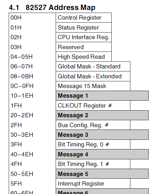
To start, we need to understand a little about the AN82527 can controller. It is memory mapped to addresses 0x80000-ff on IC501. There are 15 message objects that can be transmitted/received from the controller over the canbus.
The functions that interact with the AN82527 can be determined by looking reads/writes to this 0x80000 block.
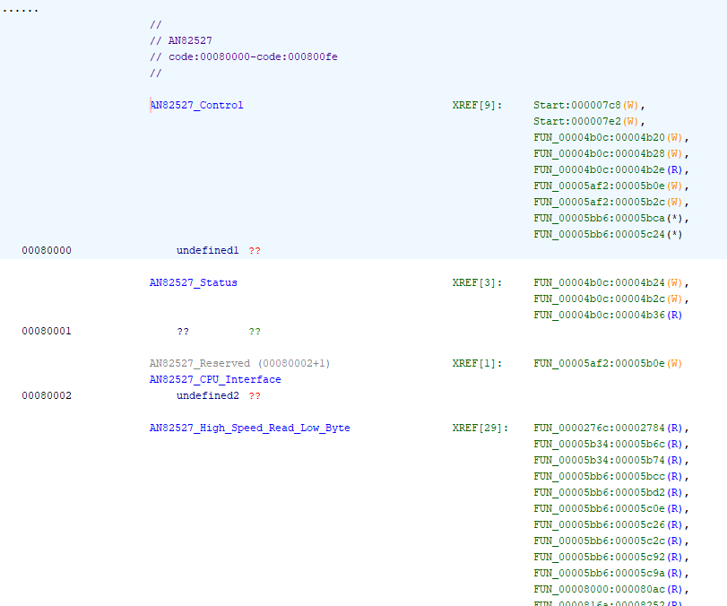
For the F27SC074 firmware these include:
- FUN 5af2, which is conditionally called from the main program loop
- FUN 5bb6, which is called from FUNs 48ca, 4994, 4a4a, 4aae
- FUN 5b34, which is called from FUNs 48ca, 4994, 4a4a, 4aae
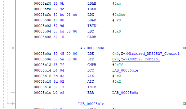
Review of FUN 5af2 shows that it copies the contents of 256 bytes of a memory block located at 0xb03ce to the 0x80000 block. So it seems that this ‘mirror’ RAM block is used to update message objects for send and receive, as well as to setup basic configuration such as message IDs for the objects)
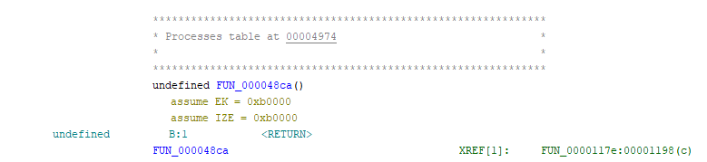
Since both FUNs 5bb6 and 5b34 are called by the four functions 48ca, etc., let’s take a look at FUN 48ca
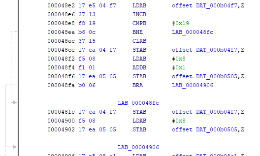
After conditional tests (not shown) a variable b04f7 is incremented, and if >= 0x19 then it is set to 0. So this variable cycles through the values 1-24. Also we can see that for values 1-23, variable b0505 is set to 8 and for value 24 it is set to 9. Then (not shown) after checking that a special ECU test mode is inactive, the Y register is set to the value 0x04976 which is a data table start address.
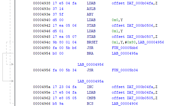
The first byte of the first table entry is copied into b0506 and the second byte into b0507. Then if bit 7 of the second byte is clr, FUN 5bb6 is called, otherwise FUN 5b34 is called. The routine then goes to the next entry in the table and does the same thing. It works through 8 or 9 table entries, depending on the value of b0505 which was set to 8 or 9 previously. The table contents are:
| table entry | high byte | low Byte | bit 7 low byte | low nibble low byte |
|---|---|---|---|---|
| 0 | 0x20 | 0x86 | set | 6 |
| 1 | 0x50 | 0x88 | set | 8 |
| 2 | 0x10 | 0x04 | clr | 4 |
| 3 | 0x30 | 0x06 | clr | 6 |
| 4 | 0x40 | 0x07 | clr | 7 |
| 5 | 0x70 | 0x06 | clr | 6 |
| 6 | 0x90 | 0x08 | clr | 8 |
| 7 | 0xa0 | 0x07 | clr | 7 |
| 8 | 0x80 | 0x88 | set | 8 |
Analyzing routines 5bb6 and 5b34, which I will skip here, show that:
- 5bb6 reads messages with object ID in b0506, and length in (b0507 & 0x0f), by copying from AN82527 to mirror RAM
- 5b34 transmits messages, with msg object ID in b0506, and length in (b0507 & 0x0f), by copying from mirror RAM to AN82527
The end result of this is that FUN 48ca does the following:
- Transmit message object 2, length 6
- Transmit message object 5, length 6
- Receive message object 1, length 4
- Receive message object 3, length 6
- Receive message object 4, length 7
- Receive message object 7, length 6
- Receive message object 9, length 8
- Receive message object a, length 7
- (every 24th iteration) Transmit message object 8, length 8
What function calls FUN 48ca?
We can see the annotation XREF[1]: FUN_0000117e:00001198(c), and if we double click on 117e we go to that function.
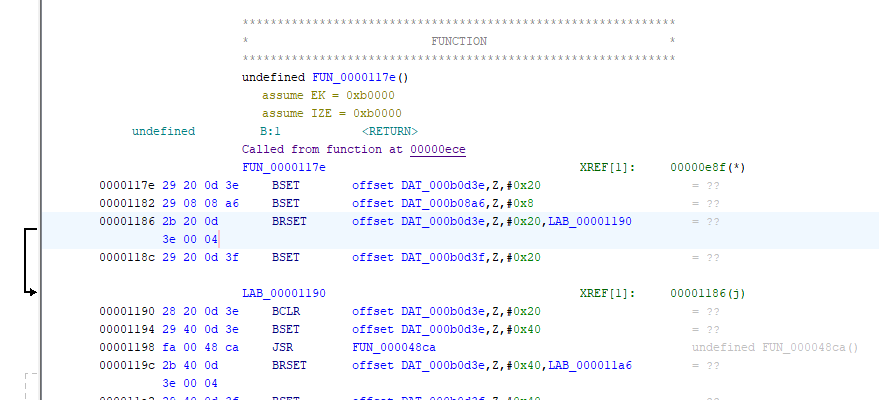
More analysis reveals that this function is called from an indirect subroutine call at address 0x00ece, using a jump table at 0x00e8a, and that this function is an interrupt service routine for the Configurable Time Module - Sub module PWMSM10, which is triggered every 2 ms. Fun 177e is called on every fourth iteration of this ISR, so is called every 8 ms. So now we know that the first 8 messages above are sent/received every 8 ms, and the last is sent every 8*24=192 ms.
The other 3 functions do similar things
- FUN 4994: TX msg b (1 byte) every 384ms, Rx messages 6 (3 bytes) and c (8 bytes) every 16 ms
- FUN 4a4a: TX msg d (8 bytes) every 32 ms
- FUN 4aae: RX msg e (1 byte) every 64 ms, RX msg f (1 byte) (support multiple IDs) every 64 ms
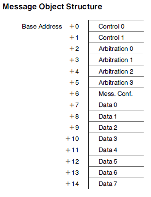
To see what these messages might be, we can head over to the RAM area at 0xb03ce and see what functions access these locations. The memory organization for a message object is as below.
For message 1, the Canbus message ID is configured by FUN 44d4.
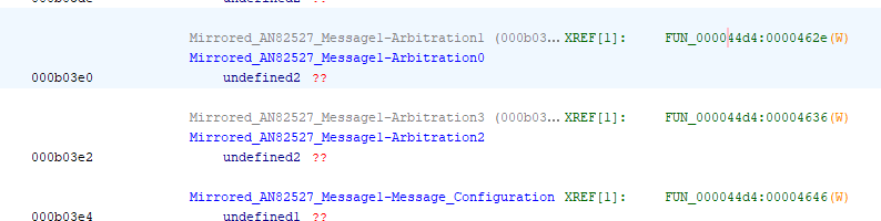
And this is true for all the messages, so a review of FUN 44d4 should provide info on what the canbus message IDs are.
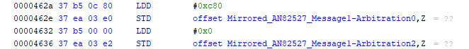
Message 1 ARB1/0 is set to 0x0c80. Arbitration 0 contains high bits for the 11 bit identifier. Arbitration 1 contains the lowest 3 bits, stored as bits 7, 6, 5. So, in bit format, if we take the word 0x0c80 and truncate the last 5 bits, we will get the canbus message ID.
0000 1100 1000 0000 > truncated and right justifed is 000 0110 0100 = 0x064.
If we do this for all the messages, we get the following data:
| msg | Arb 1/0 | Canbus ID | Direction | Length (bytes) | Period (ms) |
|---|---|---|---|---|---|
| 1 | 0x0c80 | 0x064 | Receive | 4 | 8 |
| 2 | 0x12c0 | 0x096 | Transmit | 6 | 8 |
| 3 | 0x1900 | 0x0c8 | Receive | 6 | 8 |
| 4 | 0x1f40 | 0x0fa | Receive | 7 | 8 |
| 5 | 0x2580 | 0x12c | Transmit | 6 | 8 |
| 6 | 0x3e80 | 0x1f4 | Receive | 3 | 16 |
| 7 | 0x7d00 | 0x3e8 | Receive | 6 | 8 |
| 8 | 0x8980 | 0x44c | Transmit | 8 | 192 |
| 9 | 0x9600 | 0x4b0 | Receive | 8 | 8 |
| a | 0x3200 | 0x190 | Receive | 7 | 8 |
| b | 0xfa00 | 0x7d0 | Transmit | 1 | 384 |
| c | 0xfd00 | 0x7e8 | Receive | 8 | 16 |
| d | 0xfd80 | 0x7ec | Transmit | 8 | 32 |
| e | 0xfa20 | 0x7d1 | Receive | 1 | 64 |
| f | 0xfa40 | 0x7d2/3 | Receive | 1 | 64 |
Comparing list with the known activity on the canbus, posted here (download CAN Bus messages 2001-2002 XK8 20191009a.xlsx), we have a fairly good match, which is comforting. The AN82527 operation of message object 0xf is different from the others, so some anomalies are expected there.
| ID | Source | Bytes | Cycle time (ms) | Description |
|---|---|---|---|---|
| 0x064h | ABS | 3 | 8 | Traction control torque intervention requests (best guess). |
| 0x096h | ECM | 6 | 4 | Cruise control speed setpoints |
| 0x0C8h | TCM | 6 | 10 | Transmission speed sensors (input/output) torque converter slip. |
| 0x0FAh | ABS | 7 | 8 | Vehicle speed and rolling distance counter |
| 0x12Ch | ECM | 8 | 4 | Engine pedal and throttle positions; Engine RPM |
| 0x1F4h | INST | 4 | 10 | Fuel Level and status of headlight and side markers |
| 0x3E8h | TCM | 6 | 10 | Transmission gear engaged, Trans oil temp |
| 0x44Ch | ECM | 8 | 100 | Engine Coolant Temp, Engine Oil Temp, Fuel Consumed (based on injector duty cycle). |
| 0x4B0h | ABS | 8 | 8 | ABS Module - Individual wheel speeds |
| 0x7D0h | ECM heartbeat? | 1 | 200 | ECM heartbeat |
| 0x7D1h | TCM heartbeat? | 1 | 215 | TCM heartbeat |
| 0x7D2h | INST heartbeat? | 1 | 200 | INST heartbeat |
| 0x7D3h | ABS heartbeat? | 1 | 200 | ABS heartbeat |
In the next post I’ll dig into the details of the OBD2 modes/UDS modes supported, and investigate the mode1/mode22 PIDs to identify key variables.