AJ27 ECU Hardware Schematic
In this post I will take a quick tour around the hardware schematic of the Jaguar AJ27 ECU to investigate some of the features, and provide a view of a mid/late 90s ECU design. As a refresher, the ECU uses dual Motorola 68HC16 processors and controls the Jaguar 4.0 liter V8 AJ27 engine. Images in this post are from a rough schematic created using KiCad, through images and tracing of a PCB. The schematic is approximate at best, misses off quite a few components especially decoupling capacitors, makes best guesses on a number of others such as transistors and diodes, and needs some clean up where spurious nodes have been added by sloppy editing, etc.
The canbus interface is implemented using an Intel AN82527 Can controller.
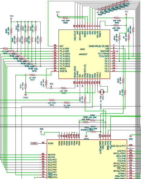
Notable features here are connection to the Main CPU (IC501) via an 8 bit data bus (pins 31-38 on the left of the AN82527), and addressing with the use of the lower 8 lines of the address bus (on the top of the AN82527, pins 2-4 and 39-43). The use of the CSA (Chip Select A) line from the CPU means that the can controller is memory mapped into the CPU address space. This provides read/write access of the CPU to 256 bytes of RAM within the AN82527 address map. Also not visible on this snapshot, Port 2 of the AN82527 on pins 10-17 is used for generic input/output.
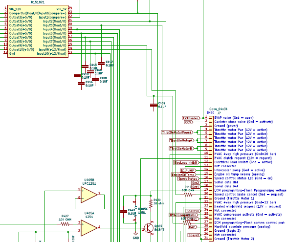
A proprietary Denso part (D151821) is used to buffer inputs to the CPU, and also interface a couple of 12V inputs to the 5V required for the processor. A couple of these devices are used in the ECU, and one is shown in the above snapshot. It is used to buffer various inputs, including in this example from the EM80 ECU connector, such as EM80-20 for Speed control brake cancel, and EM80-27 for ECM programming flash comms control port.
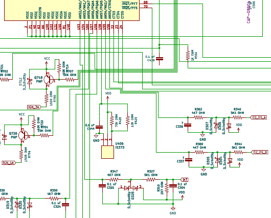
The analog to digital inputs on the CPU shown at the top of this snapshot (pins 153-160) are connected via some basic protection circuitry to the relevant sensors on the engine. A good example is at the bottom of this image, showing the Intake Air Temperature (IAT) sensor input, which connects the CPU AN53 ADC input (pin 154). Another example is the Barometric pressure sensor (IC406) which connects to the CPU AN57 ADC input. The downstream oxygen sensors for banks A and B (O2_DS_A and O2_DS_B) also connect to ADC inputs. Also seen on this snapshot are a couple of injector drivers (IGN_3A and IGN_1A) which are driven (not visible here) by outputs of the Configurable Timer Module (CTM) of the CPU.
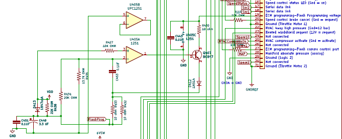
The conditioning circuit for the Flash programming voltage can be seen in the above image. It ensures that the voltage is not applied unless the CPU is powered up, and is regulated via the OpAmp/NPN transistor(BC847)/protection diode to a voltage of about 12.2V, as long as the raw input voltage is about 15.3V or higher.
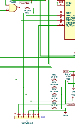
The Background Debug Mode interface to the secondary CPU is shown above. Both CPUs have break out pads for a BDM interface on the PCB. Also visible on this image in the top left is an AND gate which allows the main CPU, or the VDD power circuit on loss of watchdog signal, to force a reset of the secondary CPU.
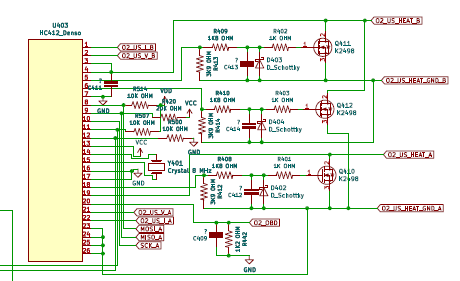
The upstream wideband oxygen sensors for the engine are processed by a proprietary Denso part, which interfaces to the Main CPU using SPI. The MOSFET drivers for the heaters can be seen on the right side of the diagram.
The overall schematic, as well as other reference material, can be found here.
The key information on connectivity can be extracted from this schematic, and summarized in a spreadsheet or similar (see the reference material link and download spreadsheet “ECU connections summary.ods” (Libre Office Format). The information is also captured below in the table.
The next post will consider initial approaches for code analysis of the CPU firmware.
| pin | Main CPU – IC501 | Sub CPU – IC601 | |
|---|---|---|---|
| 1 | VDDE | ||
| 2 | VSSE | ||
| 3 | TP0 | 501/34 (CTD22) | CKPS SIGNAL crankshaft position sensor |
| 4 | TP1 | IGNITION MODULES 1A 2B 3B 4A OBD MONITOR | CMPS, ‘A’ BANK SIGNAL |
| 5 | TP2 | IGNITION MODULES 1B 2A 3A 4B OBD MONITOR | HO2S HEATER, ‘A’ BANK DOWNSTREAM CONTROL M1 |
| 6 | TP3 | INJECTOR 1A ACTIVATE | VARIABLE VALVE TIMING SOLENOID + ‘B’ BANK C |
| 7 | TP4 | INJECTOR 2A ACTIVATE | VARIABLE VALVE TIMING SOLENOID + ‘A’ BANK C |
| 8 | TP5 | INJECTOR 3A ACTIVATE | HO2S HEATER, ‘B’ BANK DOWNSTREAM CONTROL M1 |
| 9 | TP6 | INJECTOR 4A ACTIVATE | EMSrelay |
| 10 | TP7 | INJECTOR 1B ACTIVATE | HO2S HEATER, ‘A’ BANK DOWNSTREAM CONTROL M2 |
| 11 | TP8 | INJECTOR 2B ACTIVATE | ??? |
| 12 | TP9 | INJECTOR 3B ACTIVATE | HO2S HEATER, ‘B’ BANK DOWNSTREAM CONTROL M2 |
| 13 | TP10 | INJECTOR 4B ACTIVATE | OBD2 pin 15 - Serial Communications (input only) |
| 14 | TP11 | Crank | INTERCOOLER PUMP RELAY ACTIVATE C |
| 15 | TP12 | ? | VARIABLE VALVE TIMING SOLENOID + ‘A’ BANK M |
| 16 | TP13 | 701/13 Inj 1a 2b 3b 4a | SPEED CONTROL ON STATUS LED |
| 17 | TP14 | 701/14 Inj 1b 2a 3a 4b | 501/134 IC501 port C2 |
| 18 | TP15 | AN82527 U502 interrupt output to CPU | VARIABLE VALVE TIMING SOLENOID + ‘B’ BANK M |
| 19 | T2CLK | ??? TPU clock input, | VDD |
| 20 | VFPE1 | FLASH | FLASH |
| 21 | VSSI | ||
| 22 | CTD3 | CKPS SIGNAL crankshaft position sensor | CKPS SIGNAL crankshaft position sensor |
| 23 | CTD4 | CMPS, ‘A’ BANK SIGNAL | CMPS, ‘A’ BANK SIGNAL |
| 24 | CTD5 | CMPS, ‘B’ BANK SIGNAL | CMPS, ‘B’ BANK SIGNAL |
| 25 | CTD6 | IGNITION MODULE 1A SWITCHING | 903/4 H bridge throttle |
| 26 | CTD7 | IGNITION MODULE 2A SWITCHING | 903/7 H bridge throttle |
| 27 | CTD8 | IGNITION MODULE 3A SWITCHING | 903/23 H bridge throttle |
| 28 | CTD14 | IGNITION MODULE 4A SWITCHING | 903/10 H bridge throttle |
| 29 | CTD15 | IGNITION MODULE 1B SWITCHING | EGR STEPPER MOTOR ‘S1’ WINDING SUPPLY C |
| 30 | CTD16 | IGNITION MODULE 2B SWITCHING | EGR STEPPER MOTOR ‘S2’ WINDING SUPPLY C |
| 31 | CTD17 | IGNITION MODULE 3B SWITCHING | EGR STEPPER MOTOR ‘S3’ WINDING SUPPLY C |
| 32 | CTD18 | IGNITION MODULE 4B SWITCHING | EGR STEPPER MOTOR ‘S4’ WINDING SUPPLY C |
| 33 | CTD20 | ??? | ??? |
| 34 | CTD22 | 501/3 (TP0) | VDD |
| 35 | CPWM9 | FUEL PUMP RELAY ACTIVATE C | VDD |
| 36 | CPWM10 | THROTTLE MOTOR POWER RELAY ACTIVATE?? | HO2S HEATER, ‘A’ BANK DOWNSTREAM CONTROL C |
| 37 | CPWM11 | ??? | HO2S HEATER, ‘B’ BANK DOWNSTREAM CONTROL C |
| 38 | CPWM12 | evap c | VDD |
| 39 | CPWM13 | AIR ASSIST CLOSE VALVE ACTIVATE C | VDD |
| 40 | VSSE | ||
| 41 | VDDE | ||
| 42 | CTM2C | U403 Upstream O2 (SPI chip select?) | ??? |
| 43 | TXDA/PMC7 | 601/46 | Serial Communications, Serial data link – OBD2 pin 7 (K-Line) |
| 44 | RXDA/PMC6 | 601/45 | Serial Communications, Serial data link – OBD2 pin 7 (K line) |
| 45 | TXDB/PMC5 | SECURITY ACKNOWLEDGE | 501/44 |
| 46 | RXDB/PMC4 | Ok to Start | 501/43 |
| 47 | SS/PMC3 | U202 EPROM SPI chip select | ??? |
| 48 | SCK/PMC2 | SCK | VDD |
| 49 | MOSI/PMC1 | MOSI | ??? |
| 50 | MISO/PMC0 | MISO | ??? |
| 51 | RSS/PSP7 | 601/51 | 501/51 |
| 52 | RSCK/PSP6 | 601/52, VDD 10K | 501/52 (100 OHM) |
| 53 | RMOSI/PSP5 | 601/53, VDD 10K | 501/53 (100 OHM) |
| 54 | RMISO/PSP4 | 601/54, VDD 10K | 501/54 (100 OHM) |
| 55 | RPCS0/PSP0 | PARALLEL (HIGH) SPEED FAN ACTIVATE | Cool Box Monitor |
| 56 | RPCS1/PSP1 | SPEED CONTROL BRAKE CANCEL REQUEST | SPEED CONTROL ON REQUEST |
| 57 | RPCS2/PSP2 | SERIES (LOW) SPEED FAN ACTIVATE | 903/2 H bridge throttle |
| 58 | RPCS3/PSP3 | 601/68 | 903/3 H bridge throttle |
| 59 | VSTBY | ||
| 60 | XTAL | ||
| 61 | VDDSYN/MODCK | ||
| 62 | EXTAL | ||
| 63 | VSSSYN | ||
| 64 | XFC | ||
| 65 | VDDI | ||
| 66 | VSSI | ||
| 67 | RESET | CN1-7 BDM | U501/70, U401/1, BDM CN2-7 |
| 68 | IRQ7/PF7 | 401/14 via R | 501/58 |
| 69 | IRQ6/PF6 | PARK / NEUTRAL CONFIRMATION | ??? |
| 70 | IRQ5/PF5 | Reset U601? | ??? |
| 71 | IRQ4/PF4 | AIR ASSIST CLOSE VALVE ACTIVATE M | VDD |
| 72 | IRQ3/PF3 | Reset U502 | EGR STEPPER MOTOR ‘S2’ WINDING SUPPLY M |
| 73 | IRQ2/PF2 | evap m | EGR STEPPER MOTOR ‘S1’ WINDING SUPPLY M |
| 74 | IRQX/BERR/PF1 | ??? CN1-2 BDM, CN2-2 BDM, U902, U401, BERR | THROTTLE MOTOR POWER RELAY ACTIVATE?? |
| 75 | ALE/PF0 | ECM prog – flash comms ctrl port | ECM Programming, Flash communication control port |
| 76 | D15/PG7 | U502/P1.7 | BATTERY POWER SUPPLY |
| 77 | D14/PG6 | U502/P1.6 | IGNITION SWITCHED POWER SUPPLY |
| 78 | D13/PG5 | U502/P1.5 | INTERCOOLER PUMP RELAY ACTIVATE M |
| 79 | D12/PG4 | U502/P1.4 | EM83-1 spare monitor |
| 80 | VDDE | ||
| 81 | VSSE | ||
| 82 | D11/PG3 | U502/P1.3 | VDD |
| 83 | D10/PG2 | U502/P1.2 | ??? |
| 84 | D9/PG1 | U502/P1.1 | VDD |
| 85 | D8/PG0 | U502/P1.0 | VDD |
| 86 | ACS0/PCS0 | ??? | ??? |
| 87 | ACS1/PCS1 | ??? | ??? |
| 88 | ACS2/PCS2 | ??? | ??? |
| 89 | CSA/PD7 | U502 AN82527 chip select | VDD |
| 90 | CSB/PD6 | VDD | VDD |
| 91 | CSC/PD5 | FUEL PUMP RELAY 2 ACTIVATE C | VDD |
| 92 | DTACK/PD4 | VDD | VDD |
| 93 | FREEZE/QUOT/FASTREF/PD3 | Cn1-6 bdm | Cn2-6 bdm |
| 94 | BKPT/DSCLK/CSE0/PD2 | CN1-4 BDM | CN2-4 BDM |
| 95 | IPIPE1/DS1/PD1 | CN1-8 BDM | CN2-8 BDM |
| 96 | IPIPE0/DS0/PD0 | CN1-10 BDM | CN2-10 BDM |
| 97 | D7/PH7 | U201-11 KNOCK PROCESSOR | A/CCM ELECTRICAL LOAD REQUEST (HEATED WINDSHIELD) |
| 98 | D6/PH6 | U201-16 KNOCK PROCESSOR | Canister close valve activate (CCV) M |
| 99 | D5/PH5 | U201-21 KNOCK PROCESSOR | BRAKE SWITCH |
| 100 | VSSI | ||
| 101 | CLKOUT/PE4 | U601/137 | ??? |
| 102 | VSSE | ||
| 103 | VDDE | ||
| 104 | D4/PH4 | U201-22 KNOCK PROCESSOR | SPEED CONTROL BRAKE CANCEL REQUEST |
| 105 | D3/PH3 | U201-8, 24 KNOCK PROCESSOR | A/CCM COMPRESSOR CLUTCH REQUEST (Air conditioning control module) |
| 106 | D2/PH2 | ENGINE CRANK | ENGINE CRANK |
| 107 | D1/PH1 | BRAKE SWITCH | REFRIGERANT 4-WAY PRESSURE SWITCH HIGH PRESSURE 12 bar |
| 108 | D0/PH0 | IGNITION SWITCHED POWER SUPPLY | REFRIGERANT 4-WAY PRESSURE SWITCH HIGH PRESSURE 20 bar |
| 109 | R/W/WR/PE0 | U502 R/W An82527 | VDD |
| 110 | DS/RD/PE1 | CN1-1 BDM | CN2-1 BDM |
| 111 | AS/PE2 | U201/15 knock processor (SPI CS?) | VDD |
| 112 | SIZE/PE3 | U403/12 O2 upstream | VDD |
| 113 | EBR/TSC | ??? | VDD |
| 114 | AD0/PB0 | U502 AD0 | PARK / NEUTRAL CONFIRMATION |
| 115 | AD1/PB1 | U502 AD1 | VDD |
| 116 | AD2/PB2 | U502 AD2 | VDD |
| 117 | AD3/PB3 | U502 AD3 | VDD |
| 118 | AD4/PB4 | U502 AD4 | VDD |
| 119 | AD5/PB5 | U502 AD5 | PARKING BRAKE SWITCH |
| 120 | VDDE | ||
| 121 | VSSE | ||
| 122 | AD6/PB6 | U502 AD6 | THROTTLE MOTOR POWER RELAY ACTIVATE M |
| 123 | AD7/PB7 | U502 AD7 | SPARE0 C |
| 124 | AD8/PA0 | ??? | AIR CONDITIONING COMPRESSOR RELAY ACTIVATE |
| 125 | AD9/PA1 | pull low on reset? | Null (t408) |
| 126 | AD10/PA2 | ???? | ELECTRICAL LOAD INHIBIT |
| 127 | AD11/PA3 | pull low on reset? | ??? |
| 128 | AD12/PA4 | ??? | 501/135 port C 7 |
| 129 | AD13/PA5 | ??? | SENSOR SUPPLY VOLTAGE 1 C |
| 130 | AD14/PA6 | ??? | Canister close valve activate (CCV) C |
| 131 | AD15/PA7 | ??? | “COOL BOX” COOLING FAN ACTIVATE C |
| 132 | A16/PC0 | ??? | ??? |
| 133 | A17/PC1 | ??? | ??? |
| 134 | A18/PC2 | 601/17 TP14 | ??? |
| 135 | A23/ECLK/PC7 | 601/128 PortA4 | ??? |
| 136 | FC0/PE5 | U201-31 KNOCK PROCESSOR | P2.1 |
| 137 | FC1/PE6 | U902/24 | U501/101 |
| 138 | VFPE2 | FLASH | FLASH |
| 139 | VDDI | ||
| 140 | VSSI | ||
| 141 | AN0/ANW/PQB0 | MAFS SIGNAL | TPS SIGNAL (TPS/1), 501/142 |
| 142 | AN1/ANX/PQB1 | TPS SIGNAL (TPS/1), 601/141 | TPS SIGNAL (TPS/2) |
| 143 | AN2/ANY/PQB2 | PEDAL POSITION SIGNAL (PPS/1), 601/143 | PEDAL POSITION SIGNAL (PPS/1), 501/143 |
| 144 | AN3/ANZ/PQB3 | IATS 2 SIGNAL | PEDAL POSITION SIGNAL (PPS/2) |
| 145 | AN48/PQB4 | VoltsLevel | 903/1 H bridge |
| 146 | AN49/PQB5 | ??? | SENSOR SUPPLY VOLTAGE 1 M |
| 147 | AN50/PQB6 | Flash volts measure? | Flash volts measure? |
| 148 | AN51/PQB7 | ECT SIGNAL | TPS SIGNAL (TPS/1) threshold? |
| 149 | VDDA | VDDA | |
| 150 | VSSA | VSSA | |
| 151 | VRL | VRL | |
| 152 | VRH | VRH | |
| 153 | AN52/MA0/PQA0 | SPARE4 | Spare10 |
| 154 | AN53/MA1/PQA1 | IATS SIGNAL | Spare1 |
| 155 | AN54/MA2/PQA2 | HO2S, ‘A’ BANK DOWNSTREAM | MAPS Signal (Manifold Absolute Pressure signal) |
| 156 | AN55/ETRIG1/PQA3 | HO2S, ‘B’ BANK DOWNSTREAM | SPEED CONTROL SET +/- |
| 157 | AN56/ETRIG2/PQA4 | MAFS REFERENCE GROUND2 | SPEED CONTROL CANCEL / RESUME |
| 158 | AN57/PQA5 | Barometric | VoltsLevel |
| 159 | AN58/PQA6 | FUEL TANK PRESSURE SENSOR SIGNAL | SPARE3 |
| 160 | AN59/PQA7 | Engine Oil Temp |